Solution of Additional Exercises

View Questions


Exercise 15

Wing span l = 25 m
Speed v = 1800 km/h = 500 m/s
An aeroplane flying horizontally cuts only the vertical component of the earth's field.
Dip angle, δ = 300
Vertical component of earth's field BV = B sin δ = 5 10- 4 x sin 300 = 2.5 x 10- 4
So, the potential difference between the wing tips of the aeroplane is ε = Bvvl = 2.5 x 10- 4 x 500 x 25 = 3.1 V

Exercise 16

Magnetic filed inside the solenoid,

Flux through the solenoid,

Magnitude of emf induced,

Exercise 17

Magnetic flux through the coil Φ = NBA = 500 x 0.2 x 4 x 10- 4 Wb = 0.04 Wb
Change in flux when the coil is rotated through 1800 is
ΔΦ = 0.04 – ( - 0.04) = 0.08 Wb


Exercise 18

  1. PS and QR are cutting across field lines.
  2. They are trying to drive currents in opposite directions
  3. i. SR ii. PQ
  4. The side QR is to the right of the dotted line and PS is still within the field.
  5. The flux is out of the page and decreasing.
  6. Out of the page.
  7. Anticlockwise
  8. ε = Blv = 4.0 x 10- 2 x 0.050 x 0.50 = 1.0 x 10⁻³ v
  9. I = ε / R = 1.0 x 10- 3 / 2 = 5.0 x 10- 4 A
  10. F = BIl = 4.0 x 10- 2 x 5.0 x 10- 4 x 0.05 = 1.0 x 10- 6 N
  11. 1.0 x 10- 6 N
  12. Flux = BA = 4.0 x 10- 2 x 0.050 x 0.10 = 2.0 x 10- 4 Wb
  13. t = 0.1/0.5 = 0.2 s
  14. ε = 2.0 x 10- 4 / 0.2 = 1.0 x 1- 3 V
  15. PS is on the dotted line.
  16. q = I x t = 5.0 x 10- 4 x 0.2 = 1.0 x 10- 4 C
  17. Half the current is 2.5 x 10- 4 A
  18. Half the current for twice the time = same amount of charge. 5.0 x 10- 5 C

Exercise 19

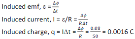
The solution of this question is based on the fact that just after closing the switch (i.e. t = 0), the induced emf or back emf is maximum and it does not allow any current to pass through the inductor. Therefore, inductor behaves as an open circuit at t = 0.

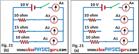
The circuit will look like as shown in figure 21 (a). But long after closing the switch (i.e. t = ∞), the induced emf or back emf becomes zero and it allows the current to pass through the inductor. Therefore, inductor behaves as a short circuit at t =∞. The circuit will look like as shown in figure 21 (b).

  1. Reading of ammeter A1 = Reading of ammeter A4 = V/R1 = 10/10 = 1 A
    Reading of ammeter A2 = 0, Reading of ammeter A3 = 0
  2. Reading of ammeter A1 = V/R1 = 10/10 = 1 A
    Reading of ammeter A2 = V/R2 = 10/15 = 0.67 A
    Reading of ammeter A3 = V/R3 = 10/10 = 1 A
    Reading of ammeter A4 = Reading of ammeter A1 + Reading of ammeter A2 + Reading of ammeter A3
    = 1 + 0.67 + 1 = 2.67 A

Exercise 20

  1. Zero
  2. Flux decreases from maximum to zero
  3. ABCD
  4. Flux increases from zero to maximum
  5. ABCD
  6. For half a turn it is in one direction and for the other half it is in the opposite direction.
  7. The coil's plane is at right angles to the field.
  8. The coil's plane is parallel to the field.


CBSE Electromagnetic Induction ( With Hint / Solution)
Class XII (By Mr. Ashis Kumar Satapathy)
email - [email protected]

Electromagnetic Induction