CBSE Electricity Subject Notes CBSE Guess > eBooks > Class X > Electricity by Mr Sanjeev
Electricity
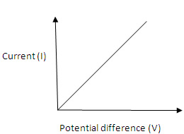
Chapter - 3 One ampere: when one coulomb of charge flows through any cross section of a conductor in one second, the electric current flowing through it will be one ampere. That is 1 ampere = 1 coulomb/ 1 second or 1 A = 1C/ 1s A smaller unit of current is called “ milliampere” is also used, which is denoted by ‘mA’. 1 mA = 10 -3 A and 1 micro ampere = 10 -6 A Note: current is measured by an instrument called ammeter and it is always connected in series of the circuit and has low resistance. Direction of electric current: the conventional direction of electric current is from positive terminal to negative terminal through the outer circuit means in the opposite direction of movement of electrons in circuit. Ohm’s law: it gives a relationship b/w current and potential difference. According to this: at constant temperature, the current flowing through a conductor is directly proportional to the potential difference across its ends. If I is the current flowing through a conductor and V is the potential difference across its ends then according to ohm’s law: Or V = R x I , where R is called “resistance” of the conductor. The value of this constant is depends on nature, length, area of cross section and temperature of the conductor. This equation can be written as follows R = V /I where , V = potential difference , I = current and R = resistance of conductor The s.i. unit of resistance of is ohm denoted by the symbol ‘Ω’. One ohm: 1 ohm is the resistance of a conductor such that when a potential difference of 1 volt is applied to its ends, a current of 1 ampere flows through it. If we draw the graph b/w current and potential difference it will always a straight line. It is clear from the following graph Good conductors, resisters and insulators: Those substances having comparatively high electrical resistance are called resisters. Like the alloys nichrome , manganin and constantan, all have quit high resistance so they known as resistances. And those substances which have infinite high electrical resistance are called insulators. An insulator does not allow electricity to flow from it. Rubber is an excellent insulator. Wood and paper are also insulator of electricity. Factors affecting the resistance of a conductor: Resistivity: It has been found that
R α l
R α 1/A From here ; resistivity (ρ) = Rx A / l Note: we use copper aluminium wires for the transmission of electricity because these have low resistivity. And the resistivity of alloys are much more higher than the pure metals. Combination of resistances:
The resistances can be combined in two ways (i) in series and (ii) in parallel
Resistances in series: when two resistances are connected end to end consecutively, they are said to be connected in series and when two resistors are connected b/w the same twp points, they are said to be connected in parallel. Resistances in series: According to the law of combination of resistances in series: the combined resistance of any number of resistances connected in series is equal to the sum of the individual resistances. For example, if a number of resistances R1, R2, R3..... etc are connected in series, then their combined resistance R is given by R = R1+ R2+ R3....
Resultant resistance of two resistances connected in series: That is : V = V1 + V2 --------------(1) We have just seen that the total potential difference due to the battery is V. Now suppose the total resistance of the combination be R, and the current flowing through the whole circuit be I. So by applying the ohm’s law Since the same current I is flows through both the resistances R1 and r2 connected in series, so by changing ohm’s law to both resistances , we will get V1 = I R1, and V2 = I R2
|
|